
-
Mail us:
editor@raftpubs.org
- ISSN : 2583-1534
Indexing & Abstracting
Full Text
Review ArticleDOI Number : 10.36811/ojrmi.2022.110046Article Views : 0Article Downloads : 1
Oblique Reconstruction: A Pictorial Follow Up
Abdulwahab Alahmari*
Radiology Specialist, Radiology Department, Al-Namas General Hospital, Ministry of Health, Al-Namas City, Saudi Arabia
*Corresponding Author: Abdulwahab Alahmari, Radiology Specialist, Radiology Department, Al-Namas General Hospital, Ministry of Health, Al-Namas City, Saudi Arabia, Tel: +966562428716; Email: afaa99@hotmail.co.uk
Article Information
Aritcle Type: Review Article
Citation: Abdulwahab Alahmari. 2022. Oblique Reconstruction: A Pictorial Follow Up. O J Radio Med Img. 5: 18-30.
Copyright: This is an open-access article distributed under the terms of the Creative Commons Attribution License, which permits unrestricted use, distribution, and reproduction in any medium, provided the original author and source are credited. Copyright © 2022; Abdulwahab Alahmari
Publication history:
Received date: 26 July, 2022Accepted date: 02 August, 2022
Published date: 05 August, 2022
Abstract
A previusly published paper about the common mistakes radiographers make when they are doing a reconstruction of a CT scan. This mistake is using the table top as a refernece, not the the oblique reconstruction according to the direction of the organ being scanned. In this paper, a proposal of going one more step further and started appling the oblique reconsutruction according to the anatomy of a region in order to get a better view. This paper will apply the oblique reconsrtuction in areas that never been used in -as the classical way of prefurming- reconstructions. These regions are: the rib cage, the spine, the great vessels, the pelvis, the calcenous bone, etc.
Keywords: Computed Tomography; Oblique Reconstruction; Parallel Reconsutruction; Region of Intrest; Volume Rendering Technique
Introduction
A previous paper was published about the most common mistake among CT radiographers which is doing the reconstruction of the slices using the table top as a refernce, not according with the organ that is being imaged 1,2. There are many regions that is not required to use the oblique reconstution with it like the rib cage. But if the oblique reconstruction is used with the rib cage, it will show the entire or a big part of one rib seen one section which will prevent missing of any fracture. As well, the reconstruction will be parallel to the lung because the lungs are taking the ribs’ shape. The difference between the oblique reconstruction and the classic way of doing reconstruction as what is seen in (Figs. from 1 thru 5). It is seen on the oblique reconstruction that one rib can be seen starting from the vertebra until the end, while on the axial straight cuts that show different segments of different ribs on each slice.
A- Rib Cage
The ribs can be domenstrated one by one as a big part of the rib in each slice. This will allow following one rib from the beginning of the rib to the end without missing any frcature or any pathology. In cases where volume rendering technique (VRT) is not avaliable, this way of reconstruction will be a great help see (Figs. from 1 thru 5).
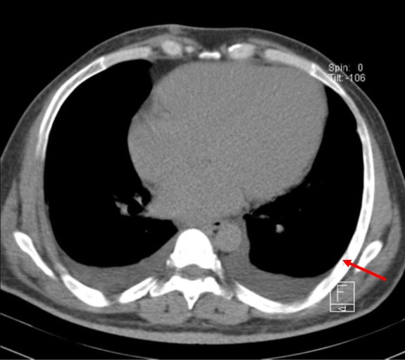
Figure 1: An axial CT scan Shows a big segment of the rib on the left side as one piece to prevent missing any fracture (the red arrow), in cases where VRT is not available.
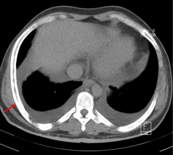
Figure 2: An axial CT scan shows a big segment of the rib on the right side as one piece to prevent missing any fracture (the red arrow), in cases where VRT is not available.
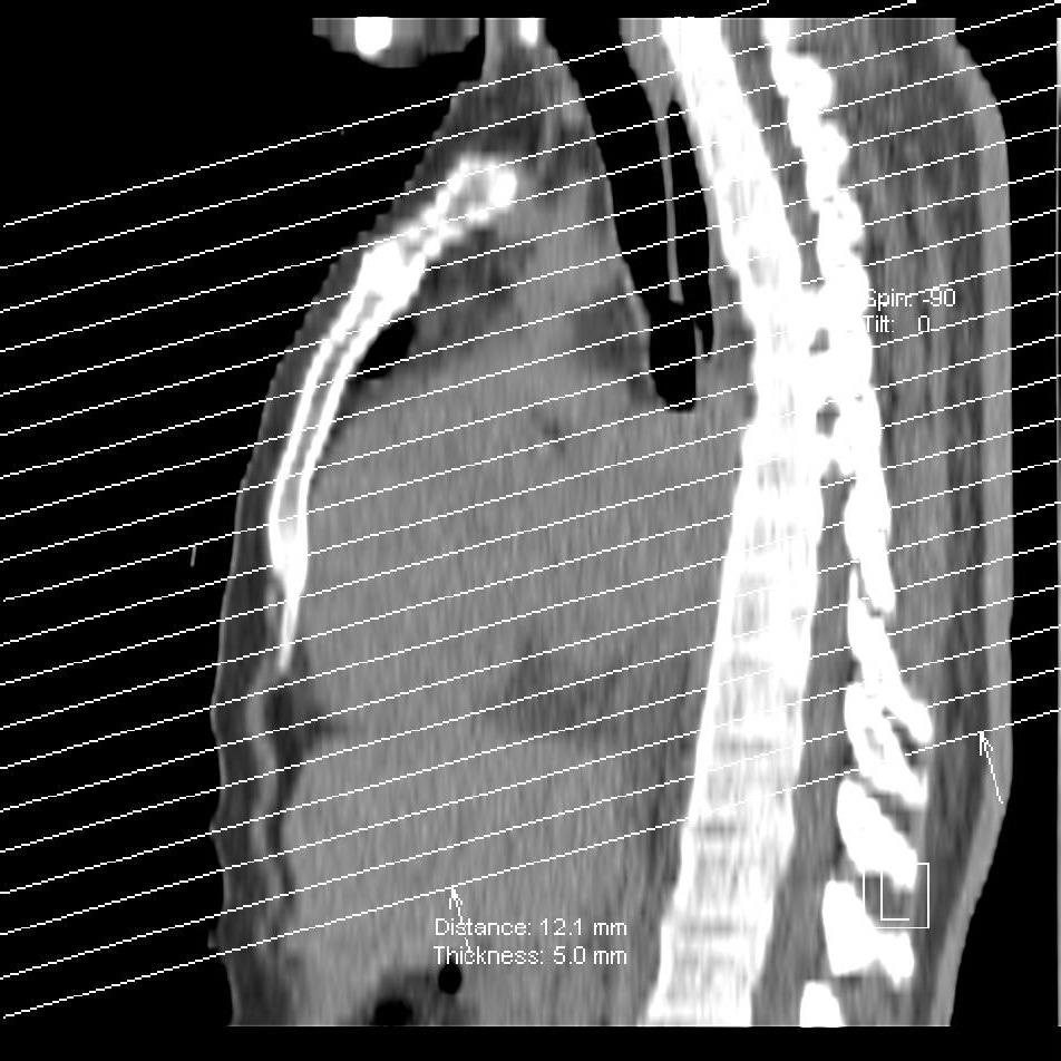
Figure 3: A sagittal CT scan Localizer and sections level reference shows the levels of the sections where are they taken.
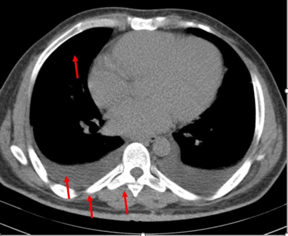
Figure 4: An axial CT scan shows different parts of different ribs due to using of straight sections.
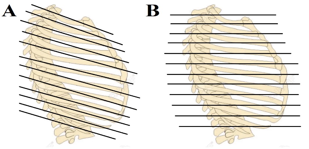
Figure 5: The level and orientation of the sections taken applied on the rib cage. The (A) illustration shows tilted lines which goes along with the ribs to take them in one section as possible. The (B) illustration shows the classic way of taking sections on the CT scan which will result in cutting three or even more ribs in one slice which will not allow seeing the continuity of the rib.
B- Spine
The cervical, thoracic, lumbar, scarum, and coccyx spine can be tricky because it has a lordotic and kyphotic curvautures, so separate reconstruction for the spine can be helpful by taking the three direction of the lordosis or kyphosis see (Figs. 6 thru 8). For example, the upper segment of the thoracic spine will be dircted downward, the middle segment of the thoracic spine will be straight, and the lower segment of the spine will be directed upward. Therefore, a three type of reconstuction can be done which will cut these vertebras at accurate levels and parallel to the vertebra direction.
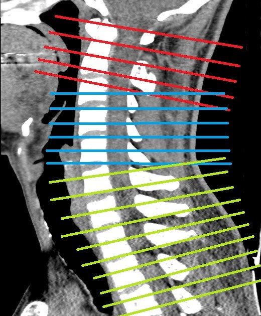
Figure 6: A sagittal CT scan of the neck with different three types of reconstruction directions according to the direction of the cervical vertebras.
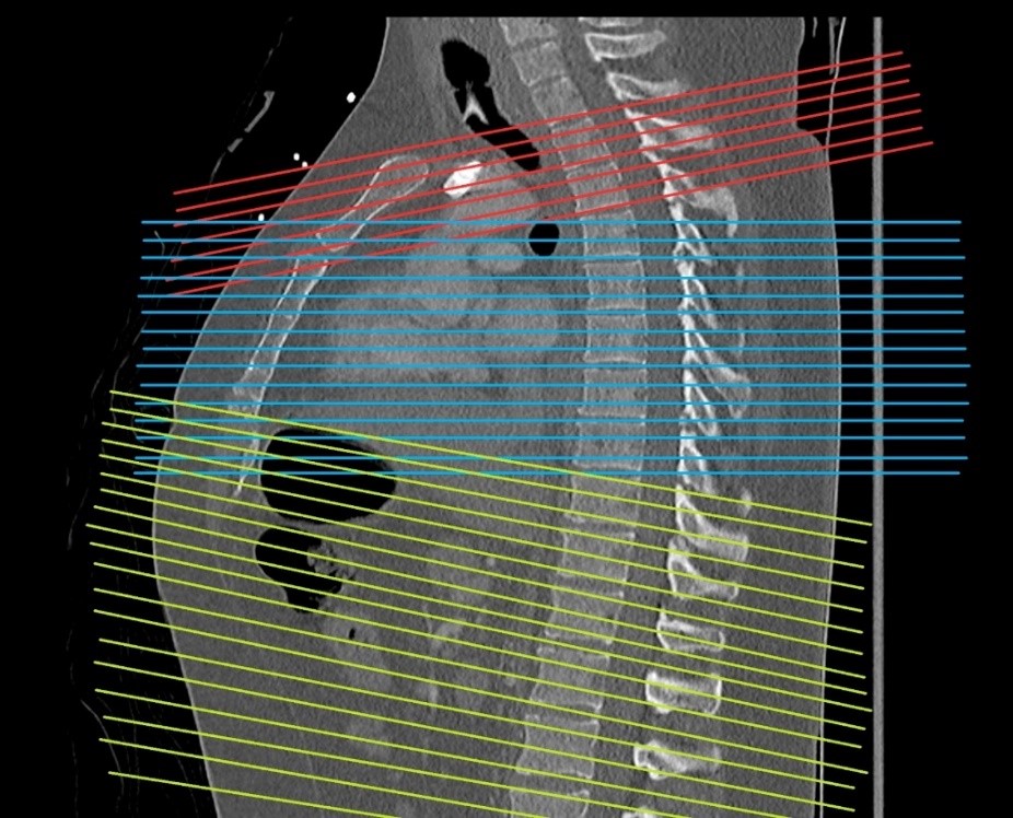
Figure 7: A sagittal CT scan of the chest shows three orientations of the directions of the reconstruction in different colors. The directions are made parallel to the spine direction.
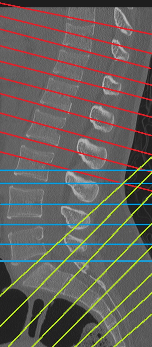
Figure 8: A sagittal CT scan of the lumbosacral spine shows three directions of the reconstruction based on the vertebra’s orientation.
C- Great vessels
In many instances, a great vessel might be the region of interest (ROI) for presence of a pathology or anything else. The great vessel might be diagonally oriented. On straight cuts, the vessel will not appear in one slice. Then one might have to check other slices and connect the dots. But if a good reconstruction was done parallel to the great vessel, then the interpreter will see the whole vessel on one slice see (Figs from 9 thru 12).
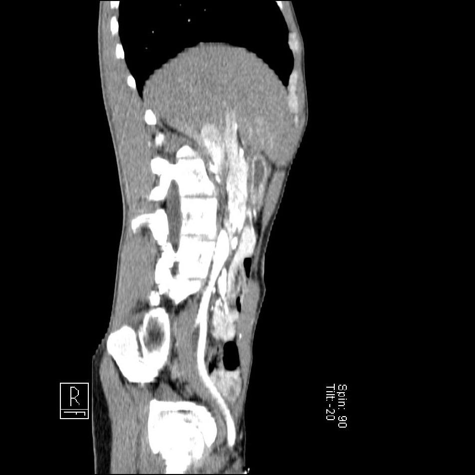
Figure 9: A sagittal CT section shows the common left iliac artery from the bifurcation of the abdominal aorta until the artery reaches the pelvis.
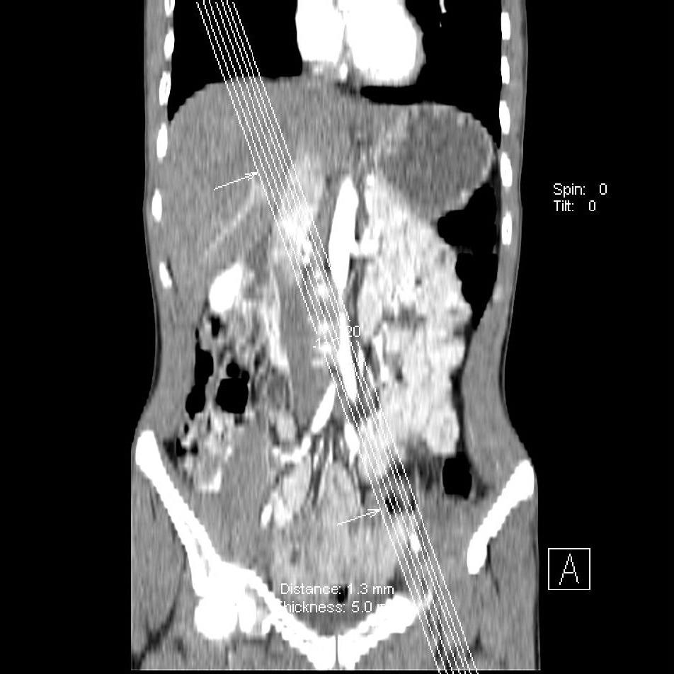
Figure 10: A coronal CT section to localize the reconstructions parallel with the common left iliac artery.
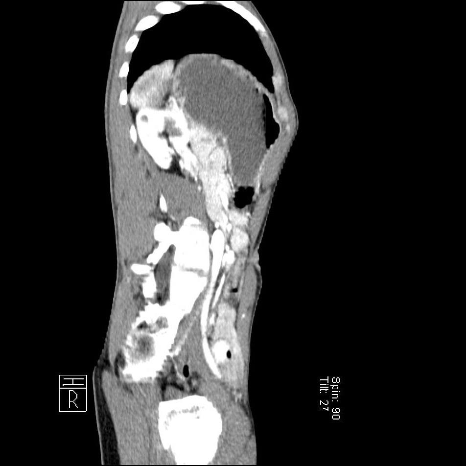
Figure 11: A sagittal section of CT scan of the abdomen shows the right common iliac artery.
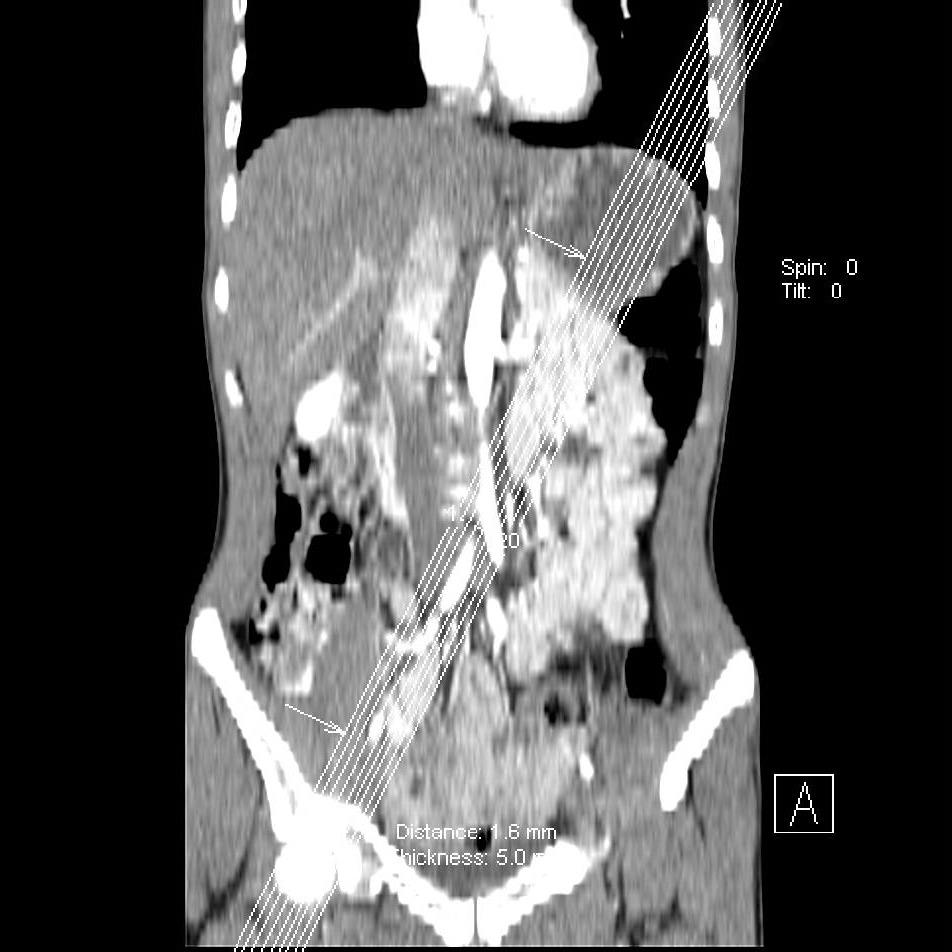
Figure 12: A coronal CT scan to localize the plan of reconstructions based on the common right iliac artery’s direction.
D- Pelvis
The pelvis in standing position is in a position where the anterior superior iliac spine is perpendicular to the pelvic tubercle which make the pelvis oriented in antero-inferior fashion. The pelvic perineum is horizontal between the symphysis pubis and the coccyx. Therefore, the reconstruction of the pelvis should be parallel to the pelvis orientation in order to get better images than the ones usually done by a simple reconstruction based on the table tope as a landmark.
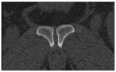
Figure 13: A coronal section of the symphysis pubis joint.
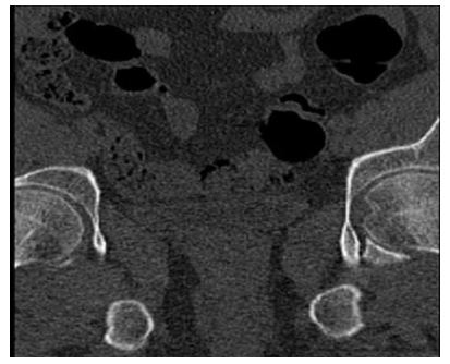
Figure 14: A coronal section of the pelvis shows both acetabula and fovea on the left side.
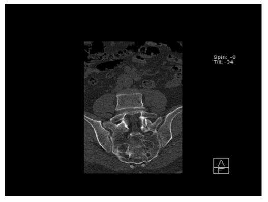
Figure 15: A coronal section of the sacrum.
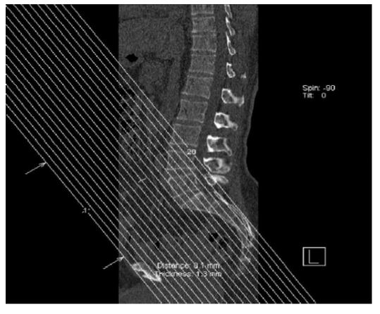
Figure 16: A sagittal section of CT scan on the pelvis (bone window) to plan the coronal reconstruction sections according to the pelvis direction.
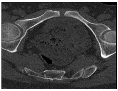
Figure 17: An axial CT scan of the pelvis according to the pelvis direction.
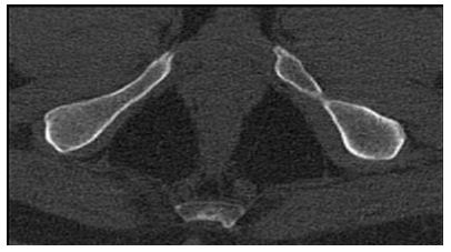
Figure 18: An axial section of the pelvis shows the floor of the pelvis.
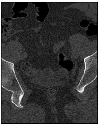
Figure 19: An axial CT scan of the rectum according to the pelvis direction.
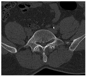
Figure 20: An axial CT scan of the pelvis shows the psoas muscles.
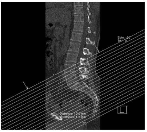
Figure 21: A sagittal section of the CT scan (bone window) to localize the direction of the “axial” sections according to the pelvis direction.
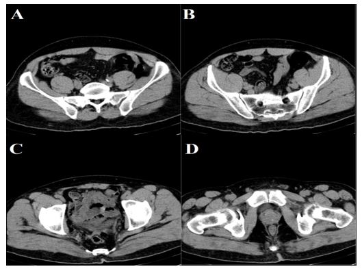
Figure 22: Compare the previous views with the regular axial CT scan of the pelvis.
E- Foot
The foot is a little bit different because it depends on the foot type. If it is a flat foot then a simple straight reconstruction is needed, but if the patient has a high arched foot (both medial and lateral longitudinal arches are high), then apply what is suggested in this paper. This can be seen on a standing X-ray (i.e., the flat foot and the arched foot). So, if the foot is highly arched or a normal foot, then this type of reconstruction will be perfect see (Fig. 23). If the patient has a flat foot, then the reconstruction will be for the whole foot as one part on the same level. The reconstruction is required in a normal arched foot and highly arched foot because the foot is divided into two parts and if reconstruction is done for both segments as a one segment then the foot image will be very useless. The reconstruction of the sagittal is the only one reconstruction that can be done for the whole foot as one segment, but the axial and coronal sections will be not of a great help because it takes the table top as a reference for the reconstruction. The foot will be in different sections and VRT will be required. If VRT is not available, the best thing to do is the oblique reconstruction for two segments (i.e., each one alone).
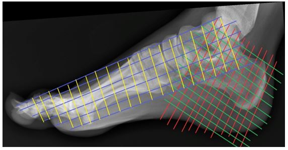
Figure 23: A lateral foot X-ray to show how the reconstruction should be done for the foot. The red and green are the calcaneus’ reconstruction plans. The blue and yellow are the rest of the foot reconstruction.
Conclusion
The oblique reconstruction is helpful in many regions like rib cage, spine, great vessels, pelvis, and feet. As well, brain, shoulder, hip, heart, knee, any great vessel of the heart, and temporal bone. Oblique reconstruction can be used with all of them.
References
1. Abdulwahab Alahmari. 2021. Importance of the oblique reconstruction of CT scan MPR formatting: A pictorial review. O J Radio Med Img. 4: 868-873.
2. Alahmari A. 2022. Importance of the Oblique Reconstruction of CT scan MPR Formatting: A Pictorial Review. Clin Res Neurol. 4: 01-04.